Version 1.20 1.21 of RUIS for Unity is now available for download. The below video demonstrates some of the new features that have been added since the last release; most of the new features relate to avatar body modification and support for different motion capture systems.
The RUIS toolkit is useful when developing applications for VR studies or VR experiences that employ avatars: as in the previous RUIS version, any rigged humanoid 3D models that can be imported to Unity will work as motion captured full-body avatars. They can also be easily embodied from a first person perspective when using a VR headset.
The new version has a variety of avatar modification parameters (body segment thickness, translation & rotation offset, etc.) that can be used to customize the avatars. The parameters can be scripted and adjusted in real-time to create body morphing effects.
In contrast to the previous RUIS versions which worked mainly with Kinect v1 and v2, the new version makes it easy to utilize any motion capture systems, whether optical- (e.g. OptiTrack, Vicon) or IMU-based (e.g. Perception Neuro, Xsens). These full-body motion capture systems can be paired to work with any VR headsets that are supported by Unity, so that the headset pose is tracked with its tracking system; this is in contrast to existing solutions offered by e.g. OptiTrack and Vicon, which required you to use their motion capture system to track everything, including the VR headset. That results in added latency and inability to utilize time/space-warp features of Oculus or HTC Vive.
As it is, this newest RUIS version is a bit rough around the edges and still contains a lot of legacy stuff that manifests itself as ~100 deprecation related warnings upon compilation. I hope to release a new version during summer, which fixes or mitigates remaining issues.
The documentation contains further information on this new release. Below you can find excerpts of the documentation, shedding light on the new features.
Controlling an avatar with a mocap system
This section describes how to use an arbitrary full-body motion capture system to control your avatars. You may skip the whole section if you are using Kinect v1 or v2. Read this section carefully if you are using Perception Neuron, Xsens, OptiTrack, Vicon etc.
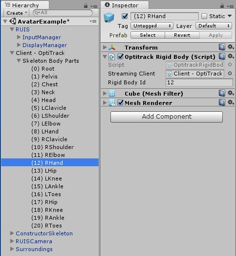
Below cropped screenshot of Unity Editor presents an example of using OptiTrack motion capture system to animate avatars in real-time with RUIS. First, you need to import the Unity plugin of your mocap system into your project. Then create GameObjects for each mocap tracked body joint, whose Transforms will be updated with the world position and rotation of the tracked joints.
In this example the joint pose updating is achieved via the OptitrackRigidBody script, that comes with the MotiveToUnity plugin. In the case of OptiTrack, stream the skeleton as individual rigid body joints instead of streaming the skeleton data format, because the joint position data is not used in the OptiTrack plugin’s own example scene where the whole skeleton object is streamed. When using OptiTrack you should also write a script that finds out the streamed rigid body joint ID numbers and assigns them to all the OptitrackRigidBody components upon playing the scene. Please note that there is no “AvatarExample” scene (as seen on the screenshot) within the RUIS project. You could use e.g. the MinimalScene example as a starting point for your avatar experiments in RUIS.
Your avatar GameObject has to have the RUISSkeletonController script. At first use the ConstructorSkeleton prefab as a ready made example, and make sure that your scene also includes the RUIS prefab that contains the InputManager and DisplayManager.
When using other motion capture systems besides Kinect, you need to make sure that the “Body Tracking Device” field is set to “Generic Motion Tracker” in RUISSkeletonController. Also disable the “Filter Rotations” option, or adjust the “Updates Per Second” property to match the mocap system update rate if you absolutely need rotation filtering. Note the two settings pointed by the magenta arrows, which should be enabled when using a IMU mocap suit (e.g. Perception Neuron, Xsens) together with a head-mounted display.
![]()
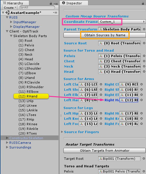
Scroll down in the RUISSkeletonController script Inspector to see the “Custom Mocap Source Transforms” -section, which is only visible if “Body Tracking Device” is set to “Generic Motion Tracker”. Give RUISSkeletonController component access to the aforementioned GameObjects (that will be updated with the world position and rotation of the mocap tracked joints) by linking their parent to the “Parent Transform” field, and clicking the “Obtain Sources by Name” button (indicated by yellow rectangle). Be sure to double-check that the results of this automatic linking process are correct. Alternatively, you can drag the individual GameObjects into the corresponding “Custom Mocap Source Transforms” fields, as exemplified by the magenta arrow in the below image. Some of the fields can be left to “None”, but we recommend that you link all available mocap tracked joints; at least Source Root, Pelvis, Shoulders, Elbows, Hands, Hips, Knees, and Feet.
The avatar should make a T-pose in Play Mode, when the mocap tracked joint GameObjects all have an identity world rotation (0, 0, 0) and their world positions correspond to that of a T-pose. Your mocap system plugin might not input joint poses in that format. In that case the joint GameObjects should have child GameObjects with a rotation offset that fulfills the T-pose requirement, when the child GameObjects are linked to the “Custom Mocap Source Transforms” fields instead of their parents. This method can also be used to create joint position offsets.
Note the “Coordinate Frame [and Conversion]” field outlined by the magenta rectangle. That setting associates a specific coordinate frame (“Custom_1”) with the avatar and its mocap system, which allows applying any coordinate alignment and conversions that are required to make the avatar function properly in Unity and together with other input devices supported by RUIS. If you are using Perception Neuron, leave this property to “None”.
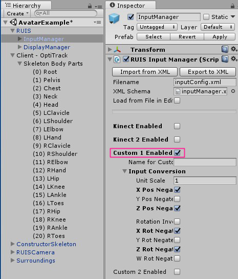
To access the coordinate conversion settings, you should enable the associated “device” (Custom 1) from the RUISInputManager component, which is located at the InputManager gameobject (parented under RUIS gameobject). You only need to adjust these settings if the avatar ends up being animated wrong, for example if the joints point at different directions in Unity than in the motion capture software (e.g. Axis Neuron, if you are using Perception Neuron).
The below example shows what “Input Conversion” settings are needed to make avatars work properly with joint data that is streamed from OptiTrack’s old Motive 1.0 software from early 2013. Basically the input conversion is used to make the streamed motion capture joint position and rotation format to conform with Unity’s left-handed coordinate system. You can adjust the “Input Conversion” settings in Play Mode to see their effects in real-time.
At the very bottom of RUISSkeletonController component there are the Avatar Target Transforms fields that need to point to the joint Transforms of the avatar rig. In case you are using a mocap system with finger tracking, you should note that Finger Targets are not assigned in the RUIS avatar prefabs. With MecanimBlendedCharacter prefab you can click the “Obtain Targets from Animator” button, but with other RUIS avatar prefabs you need to drag and drop the transforms manually. This will be fixed for the next RUIS version. You also need to disable the “Fist Clench Animation” option.
Using a VR headset with a mocap system
If you want to implement first-person avatars by using a VR headset together with a separate, full-body mocap system, then it is best to utilize the VR headset’s tracking system for moving the virtual cameras. That will minimize motion-to-photon latency and allow time-warp optimizations. Consequently, you will then be operating two motion tracking systems simultaneously. If the mocap system is optical (e.g. Kinect, OptiTrack, Vicon), then in most cases you want to align the coordinate frame of the mocap system with the coordinate frame of the VR headset’s tracking system. An alternative to this alignment is to enable the “HMD Drags Body” and “IMU Yaw Correct” options in RUISSkeletonController, which only works if the mocap system accurately tracks head yaw rotation, ruling out Kinect v1 and v2. This alternative approach has a side effect of making the avatar “slide” if there is noticeable latency between the mocap and the VR headset tracking.
When using a VR headset, enable the “Update When Offscreen” option of the avatar’s SkinnedMeshRenderer component, for avoiding mesh blinking in first person view. In RUIS 1.21 this option is disabled by default in all RUIS avatar prefabs (will be fixed for next version).
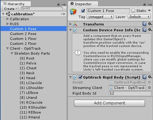
Aligning coordinate frames happens via a calibration process, which is not required when using a IMU mocap suit (e.g. Perception Neuron, Xsens) together with the VR headset. The calibration occurs in calibration.scene that comes with RUIS. When using some other mocap system than Kinect v1 or v2, then you need to edit the scene so that the “Custom 1 Pose” GameObject’s world position and rotation will have their values from a joint that will be streamed from your mocap system. If necessary, also edit the “Input Conversion” settings of the RUISInputManager component that is located at InputManager GameObject (parented under RUIS GameObject of the scene).
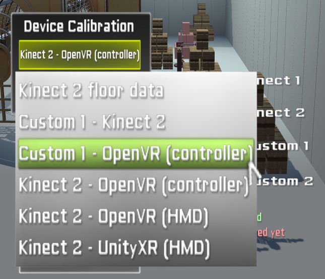
You can align the coordinate frames of two input devices by running the calibration.scene in Unity Editor; in this case just make sure that you have the intended two devices selected in the RUISCoordinateCalibration component, which is located at the Calibration GameObject of the scene. Alternatively, you can initiate the calibration process via RUIS menu, which can be accessed in Play Mode by pressing the ESC key in any of the RUIS example scenes. Use a mouse to click the green button under the “Device Calibration” label, which opens up a drop-down menu of devices that can be aligned; the available menu items depend on the enabled devices and the detected VR headset.
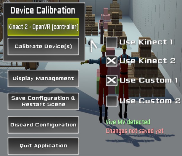
Once you have selected the device pair from the drop-down menu, click “Calibrate Device(s)” button to start the process for aligning their coordinate frames.
Avatar customization and automatic scaling
RUISSkeletonController allows the customization (affecting looks) of arbitrary avatars via relative offsets in translation, rotation, and scaling of individual body segments. These properties can be animated via scripting, which facilitates the creation of interactive effects, for-example power-ups that make the avatar’s arms bigger etc.
Below image shows the most important settings of the RUISSkeletonController component. If “Keep PlayMode Changes” (yellow rectangle) option is enabled, majority the properties are highlighted with a light yellow background during Play Mode: the values of these highlighted properties will retain their values when exiting Play Mode. This is useful because you need to be in Play Mode to see the effects of the scaling and offset properties, and the default Unity Editor behaviour is to reset all changes made to properties when exiting Play Mode.
The properties within the blue rectangle are the most significant avatar scaling options. By modifying them you can adjust body segment thickness and scaling granularity: “Scale Body” (scales whole avatar, required by all other scaling options), “Torso Segments” (scales individual torso segments), “Scale Limbs” (scales limb segments uniformly to affect their length), and “Length Only” (scales limbs non-uniformly to preserve their thickness). Limbs refer to forearms, upper arms, thighs, and shins. Enabling “Scale Body” and “Scale Limbs” options matches the avatar’s proportions with those of the user (lengthwise).
The magenta rectangle surrounds the most important “Scale Adjust” and (translation) “Offset” properties that affect the looks of the avatar’s torso and head.
![]()
Besides affecting looks, correcting retargeting issues is the secondary function of avatar body segment settings that affect translation, rotation, and scale. Such issues arise if an avatar and the utilized mocap system use different location and orientation conventions for corresponding joints. For example, mocap systems often have a specific ratio between spine bone (pelvis, chest, neck, head) lengths, which vary little between users of different height. The corresponding ratios can be vastly different for various 3D model rigs that are used as avatars.
If “Scale Body” and “Torso Segments” options are enabled, then the avatar’s spine bones will be scaled so that their lengths correspond to the input from the mocap system. This can lead to peculiar body scaling (e.g. neck gets too thin or thick), if the spine bone ratios are different between the avatar and the input from the mocap system. This can be corrected by adjusting the “Scale Adjust” or (translation) “Offset” properties of the affected bone. In similar instances with mismatched bone ratios, the avatar’s torso can look peculiar even if “Torso Segments” is disabled, in case any of the individual body segment mocap options (e.g. “Chest Mocap”) is enabled under “Update Joint Positions”. This can also be addressed by adjusting the “Scale Adjust” or “Offset” properties. Each time you switch to a new avatar or to a different mocap system, you might need to modify the avatar’s “Scale Adjust” or “Offset” properties.
Enabling the “Length Only” option for scaling works only with certain avatar rigs, where there exists a single local axis (X, Y, or Z), which points the bone length direction consistently among all the limb joint Transforms (shoulders, elbows, hips, and knees). Set “Bone Length Axis” to that axis. You can discover the correct axis by selecting individual limb joint Transforms of the rig while having the “Pivot” option of “Transform Gizmo” and “Move Tool” chosen in Unity Toolbar. This makes the “Move Tool” to indicate localScale axes of the selected joint Transform. The correct axis is the one that is aligned with the bone length direction. In some avatar rigs that alignment is not consistent among all the limb joints (e.g. many Mixamo rigs), in which case you should disable “Length Only”. In the next RUIS version you will be able to set “Bone Length Axis” separately for arms and legs, covering Mixamo rigs and others with inconsistent bone length axis directions.
The default “Max Scale Rate” of 0.5 (units per second) is too high for Kinect and other mocap systems that continuously estimate user’s bone lengths. This default was chosen because “Max Scale Rate” also limits how quickly any changes to “Thickness” and “Scale Adjust” properties are manifested in the avatar, and smaller values would have made the changes less apparent. In a future version these properties will not be limited by “Max Scale Rate”, and the default will be set to 0.01.
Finally, remember that tooltips provide additional information about the properties of RUISSkeletonController. Tooltips appear when hovering the mouse cursor over the property name in Inspector. Tooltips do not show up during Play Mode.
96gr8c